Objective
- Understand how to use queues and interrupts with
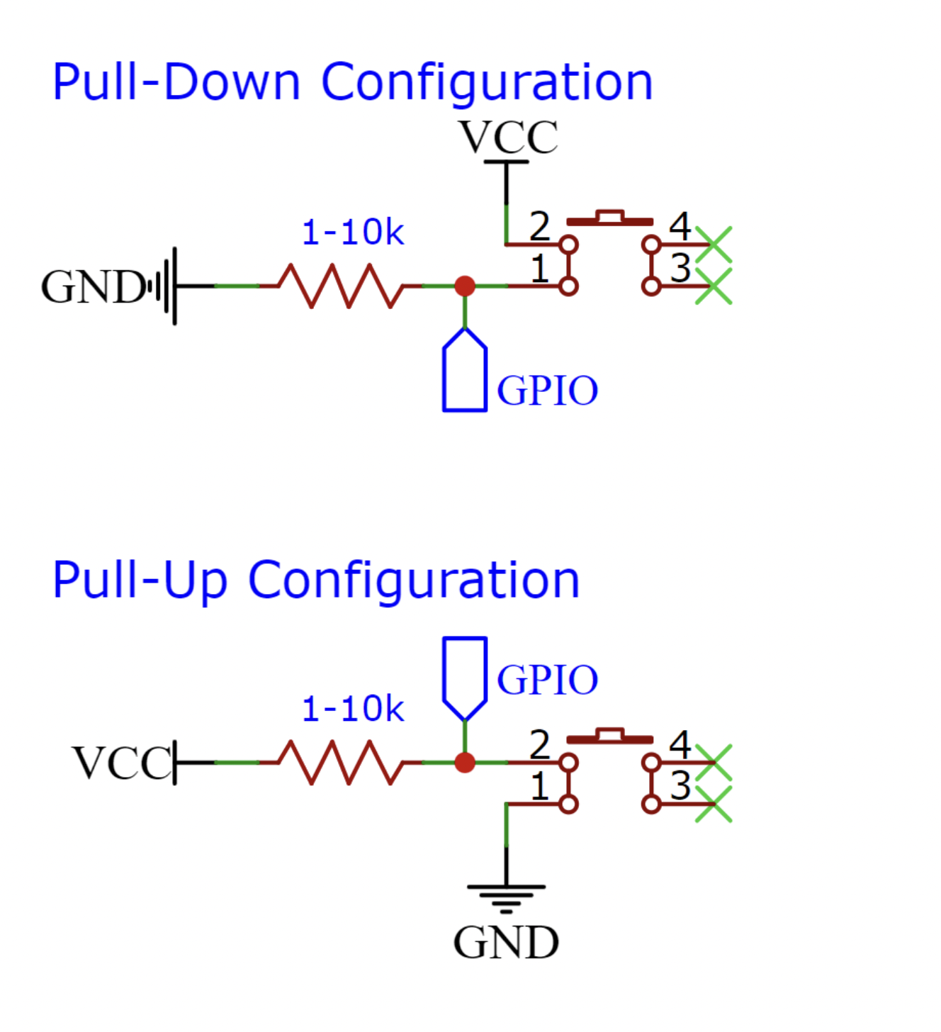
FreeRTOS Queues. In this lab, students will learn how to send data between tasks using interrupts. Student must create a program that uses gpio interrupts as in Lab 2, please feel free to use either configuration (Pull-up | Pull-down). The interrupt service routine (ISR) should send data (gpio pin number) to a queue and be receive by task: print_task. The print_task must receive the data and display it. For instance, if the interrupt was trigger by pin 23, the output would be: "GPIO 23 received!!!".
| Task | Objective |
| print_task | Receive data and print to terminal/monitor |
| Interrupt | Objective |
| gpio_isr | Send data to print_task |
Bonus
- Undergrad Bonus
- Modify code to use 2 more
interrupts.
- Grad Bonus
- Modify code to use 2 more
interrupts and add 2 LEDs. Each interrupt must toggle its corresponding LED.
ESP32 Pinout
+-----------------------+
| O | USB | O |
| ------- |
3V3 | [ ] [ ] | VIN
GND | [ ] [ ] | GND
Touch3 / HSPI_CS0 / ADC2_3 / GPIO15 | [ ] [ ] | GPIO13 / ADC2_4 / HSPI_ID / Touch4
CS / Touch2 / HSPI_WP / ADC2_2 / GPIO2 | [ ] [ ] | GPIO12 / ADC2_5 / HSPI_Q / Touch5
Touch0 / HSPI_HD / ADC2_0 / GPIO4 | [ ] [ ] | GPIO14 / ADC2_6 / HSPI_CLK / Touch6
U2_RXD / GPIO16 | [ ] [ ] | GPIO27 / ADC2_7 / Touch7
U2_TXD / GPIO17 | [ ] [ ] | GPIO26 / ADC2_9 / DAC2
V_SPI_CS0 / GPIO5 | [ ] ___________ [ ] | GPIO25 / ADC2_8 / DAC1
SCK / V_SPI_CLK / GPIO18 | [ ] | | [ ] | GPIO33 / ADC1_5 / Touch8 / XTAL32
U0_CTS / MSIO / V_SPI_Q / GPIO19 | [ ] | | [ ] | GPIO32 / ADC1_4 / Touch9 / XTAL32
SDA / V_SPI_HD / GPIO21 | [ ] | | [ ] | GPIO35 / ADC1_7
CLK2 / U0_RXD / GPIO3 | [ ] | | [ ] | GPIO34 / ADC1_6
CLK3 / U0_TXD / GPIO1 | [ ] | | [ ] | GPIO39 / ADC1_3 / SensVN
SCL / U0_RTS / V_SPI_WP / GPIO22 | [ ] | | [ ] | GPIO36 / ADC1_0 / SensVP
MOSI / V_SPI_WP / GPIO23 | [ ] |___________| [ ] | EN
| |
| | | ____ ____ | |
| | | | | | | | |
| |__|__| |__| |__| |
| O O |
+-----------------------+
Example
Here is an example of how to use ESP32 GPIO advance setup. The following code will have an external LED toggling every half second and will toggle the onboard led if the button is pressed.
#include <stdio.h>
#include "freertos/FreeRTOS.h"
#include "freertos/task.h"
#include "driver/gpio.h"
#define ESP_INTR_FLAG_DEFAULT 0
#define LOW 0
#define HIGH 1
#define ONBOARD_LED 2
#define EXTERNAL_LED 22
#define BUTTON 23
void toggle(gpio_num_t pin){
static bool on;
gpio_set_level(pin, on);
on = !on;
}
static void IRAM_ATTR gpio_isr_handler(void* arg) {
gpio_num_t gpio = (gpio_num_t) arg;
toggle(gpio);
}
void gpio_setup(void){
gpio_config_t io_conf;
io_conf.intr_type = GPIO_INTR_POSEDGE;
io_conf.mode = GPIO_MODE_INPUT;
io_conf.pin_bit_mask = (1ULL << BUTTON);
io_conf.pull_down_en = 1;
io_conf.pull_up_en = 0;
gpio_config(&io_conf);
io_conf.intr_type = GPIO_INTR_DISABLE;
io_conf.mode = GPIO_MODE_OUTPUT;
io_conf.pin_bit_mask = (1ULL <<
ONBOARD_LED) | (1ULL << EXTERNAL_LED);
io_conf.pull_down_en = 0;
io_conf.pull_up_en = 0;
gpio_config(&io_conf);
gpio_isr_handler_add(BUTTON, gpio_isr_handler, (
void*)
ONBOARD_LED);
}
gpio_setup();
while(1){
toggle(EXTERNAL_LED);
vTaskDelay(500/portTICK_PERIOD_MS);
}
}
void app_main()
Definition main.c:261
#define ONBOARD_LED
Definition main.c:31
#define ESP_INTR_FLAG_DEFAULT
Definition main.c:29
Lab Template
#include <stdio.h>
#include "freertos/FreeRTOS.h"
#include "freertos/task.h"
#include "freertos/queue.h"
#include "driver/gpio.h"
#define ESP_INTR_FLAG_DEFAULT 0
static void IRAM_ATTR gpio_isr_handler(void *arg)
{
}
{
}
{
}
{
xTaskCreate(&
print_task,
"print_task", 2048, NULL, 10, NULL);
}
QueueHandle_t xQueue
Definition main.c:72
void gpio_interrupt_setup(void)
Definition main.c:59
void print_task(void *pvParameters)
Definition main.c:53
C helpful functions
We have use queues in the previous lab to send data from one task to another. However, in this lab we need to send data from an interrupt to a task. Therefore, a special function is needed to send data to the queue: xQueueSendFromISR(). Similar to the previous lab functions that we have use to send data in a queue, xQueueSendFromISR is similar with a different parameter. To keep it simple, please set BaseType_t *pxHigherPriorityTaskWoken parameter set to NULL.
BaseType_t xQueueSendFromISR(
const void *pvItemToQueue,
BaseType_t *pxHigher PriorityTaskWoken
);
For more information of how to use Queues and Interrupts, please see previous labs.
Pull-up and Pull-down Configuration
Additional Links
Authors
GitHub
Read Next: Lab 7
